

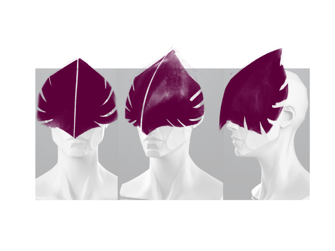


Concept design of VR headset inspired by owls + Generative design aesthetics.
Human head reference source here
ヽ(⏒⍘⏒)ノ
Concept design of VR headset inspired by owls + Generative design aesthetics.
Human head reference source here
ヽ(⏒⍘⏒)ノ
Retextures of the Alchemist


Autumn, Noir, Cthulhu, and Coffee
(งᚖ ͜ʖᚖ)ง
To print the eyes, I chose powder bed fusion, though it is not suitable for practical parts and is known for being fragile. This method would be more than suitable for creating full-colour textured spheres. Furthermore, eyes not strictly functional pieces even though they have a functional purpose and as they are small solid spheres, would be difficult to break.


The printer I used for the eye spheres is the Gypsum 660 inkjet powder bed fusion printer. I exported the sphere as a textured OBJ which also created an MTL (Material Library File). These files, as well as the original texture source image, had to be taken into Materialise Magics (Materialise, Belgium) and exported as a ZPR which is compatible with the 3D Print (3D Systems, South Carolina) software to be oriented and sent to print.


The print itself took 59 minutes and each eye contains 237 layers of powder and post-processing extended the entire process to just over a day. The models had to be removed from the powder bed and transferred to the cleaning station to remove powder with compressed air. As the pieces are solid I could use a solid bristle brush to scrub the excess off the surface without risk of breaking them.
After all excess powder was removed, the models must be hardened with cyanoacrylate infiltrant 500/ superglue. I held the models over a box and poured the glue evenly over the surface area; repeating this process twice allowed the glue to absorb into the powder to harden the overall shape. The models are then dried under the in-built heater of the cleaning station overnight before being sanded with various grades of paper. This resulted in a smoother performance from the models when moved around in the eye cups, which would benefit the eyes used in the resin models due to the sharp residue from the support structure causing some resistance when articulating the eyes. With more layers and mixing sanding techniques, the models could have a smoother finish.


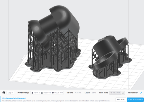
I printed a clear resin version of both the eye plate and the base holder with reduced waste material to observe the difference in material texture and density. The modifications in this design consist of removing the rounded back face for a flat surface and hollowing out the eye stems with a 10mm extrusion.
This print uses the same technology as the black resin SLS Form 2 print however it only took 6.12 hours. As this was printed prior to testing the magnets, I did not reduce the material between magnet chambers and yet the magnetic link is noticeably stronger; I consider this is due to the resin being less dense.


|◉ロ◉|


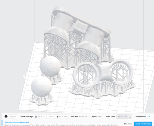
This test was SLA (Stereolithography Apparatus) printed on Form 2 (Formlabs, Massachusetts). The material is black V2 resin and the files were orientated in PreForm (Formlabs, Massachusetts)
As the material is liquid resin, any cup geometry would cause a vacuum and damage the machine. I had to carefully angle the prints to ensure there is no cupped geometry facing into the resin, consider where the support structure is and how it will affect the interior of the eyecups and the magnet chambers.


The print took 16.17 hours for both the files in the orientation shown above with an additional 30 minutes in the Form Wash bath filled with IPA (isopropyl alcohol) and 20 minutes in the Form Cure UV (ultraviolet) chamber. The support material was removed prior to the alcohol bath as it is soft and comes away easily. It also creates a softer edge with reduced sharp surface bumps left by the support structure. I tried later removing some of the sharpness however this left more abrasions on the black resin and did not contribute to the model’s function. The print turned out very successful and with the high precision of Form 2’s completely negated the PLA print as the eye plate fits cleanly into the base holder and sits flush to the eyecups. Though this print is much heavier than PLA and would need a stronger armature to hold it in place.
⤜(*ᨓ*)⤏


My first test piece took 7.31 hours and was FDM printed on the ULTIMAKER extended 3. The base holder and the removable eye plate are loaded into ULTIMAKER Cura (ULTIMAKER, Geldermalsen) and adjusted the file orientation to best suit the structural integrity of the piece. As the design printed without support material there is some stringiness and rippling in the model base.
The model is made of white PLA (Polylactic Acid) filament (GoPrint3D, Ripon) and despite an uneven finish, both the eye plate and the base slot together. However, the pieces do not fit flush together at a straight angle as the design intended; the eye plate must first be placed in vertically and turned 90°. There seems to be no clearance with this material and the pieces hold tightly together making magnets unnecessary for this version. The missing material on the back face of the eye plate causes large gaps, however, this has doesn’t appear to have affected the function of the design.


The post-processing procedure wasn’t complex however the pieces were difficult to scrape off the build plate and the frayed edges required significant clean-up. Reversing the angle of the eye plate may fix the missing material problem but may result in breakage when being removed from the build plate. The base holder is fit for purpose and very lightweight with the only issues being the sharp edges. As this piece is intended to go inside a puppet head, aesthetics is not a major issue in its usage.
( ゚ᗜ ゚)
With the intent of exploring different additive manufacturing technologies, I am creating prototypes for 3 printable artefacts. I intend to create components that assemble into 1 object.
Deciding on the main theme, I have explored aspects of historic artefacts within the realm of animation and character design. My current major project revolves around printing stop-motion armature joints for character puppets so this module would be ideal for experimentation and research.


I also created a humanoid character head with multiple iterations in an attempt to gain an editable body in Fusion 360.


Meshes do not translate well into Fusion, it seems.
( ᐛ )و


* Firefox or Chrome web browser recommended for GIFs to work *
( ͡° ͜ʖ ͡°)


I found the methods of design in Fusion 360 daunting, particularly in the early iterations of the design stage. Having lectures and fusion sessions in a class environment encouraged peer learning and far more effective troubleshooting. Having to adapt to software that is similar yet quite different in terms of technical function has been the biggest challenge for me. Though I have found difficulty in developing efficient workflows and solutions to technical problems, I have always found support from my colleagues/ faculty or with online resources.


With original concepts, I attempted to use the same methods as the Legacy Hex project by creating faces imported from Adobe Illustrator. This worked at the concept stage but in regard to placement and measuring critical components (i.e. the pin/portholes), I was unsure how to export the sketches into Illustrator, modify the design, then reimport for final assembly. With more experimentation, this would have made the design far more intricate.


The most prevalent problems have stemmed from the locking pins and the stacking indents. My design does not have a locking mechanism other than the pins which I would like to change at further development opportunities. the stacking indents are connected via projection which resulted in yellow errors shown in the figure above. I am still unsure of how exactly to remedy these without rolling back the sequence and reapplying some of the changes. I have learned not to stagger out my modifications as much as I have during this design. As you can see from my timeline, I tend to jump around the design before finalising a particular feature. This has been one of the reasons I have encountered some difficulty down the line, particularly when fixing problems relating to physical functions.
For future experimentation, I am now aware that the type of filament can also make major changes. As with the final print, the slightly thicker plastic would have solved the problems with loose locking pins however it would have still required the pin access ports to be modified.
I often take to online forums for menial problems but watching long tutorials of fully realised projects has helped in gaining new techniques for developing design functions and often reveals various ways to get a particular result suited for different situations. I began with a few videos by Nick Kloski and his beginners’ essentials to Fusion 360 on Lynda.
Now I feel far more comfortable in Fusion 360 and believe I have the necessary knowledge to adapt my learning and problem-solving abilities and overcome most of my current ‘bad habits’ for advanced modeling.
* Firefox or Chrome web browser is suggested for the GIFs to work *
~(˘▾˘~)
